4. Mesh
4.1. The Geometric Discretization of the Physical Domain
4.1.1. Mesh Quality
Obtaining a mesh for the domain is one of the primary tasks of the project. The task is achieved by discretization of the model. Discretization of the model can be expressed as generating grids in two or three dimensional geometry and results in mesh. The mesh consists discrete elements defined by a set of vertices and it is bounded by faces. The cells or elements that compose mesh system are not overlapped and completely fill the domain. The elements are bounded by faces that are possibly shared by adjacent elements, except at the boundaries. The mesh plays a vital role in accuracy of the solution and minimizing the computer resources, therefore generating a good mesh is a foremost task in any CFD simulation. The basic rules for generating mesh that followed for the project are listed below:
- All faces do not intersect each other.
- Mesh density is adequate to capture all relevant flow features.
- The mesh located at the boundary is fine enough to resolve the boundary layer flow.
- Aspect ratio, which is the ratio of longest edge length to shortest edge length of the element, is close to unity.
4.1.2. Discretization of the Coriolis Platform
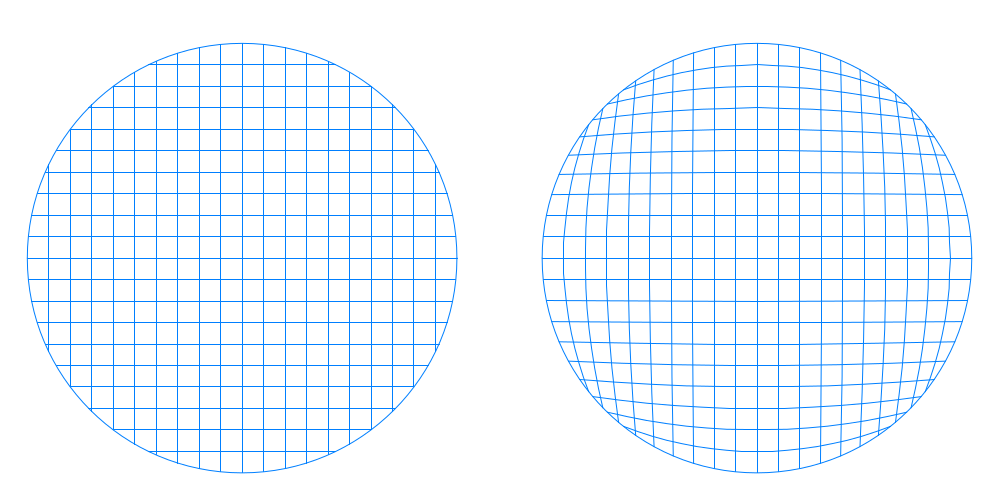
The Coriolis platform has cylindrical shape, therefore discretization of the domain is not complicated as a complex domain which has irregular geometric features. The initial grid system that can be thought at first can be similar with the figures shown below. However, when the above listed considerations are taken into account, it is observed that the aspect ratios of the faces close to the boundary are in conflict with the rule.
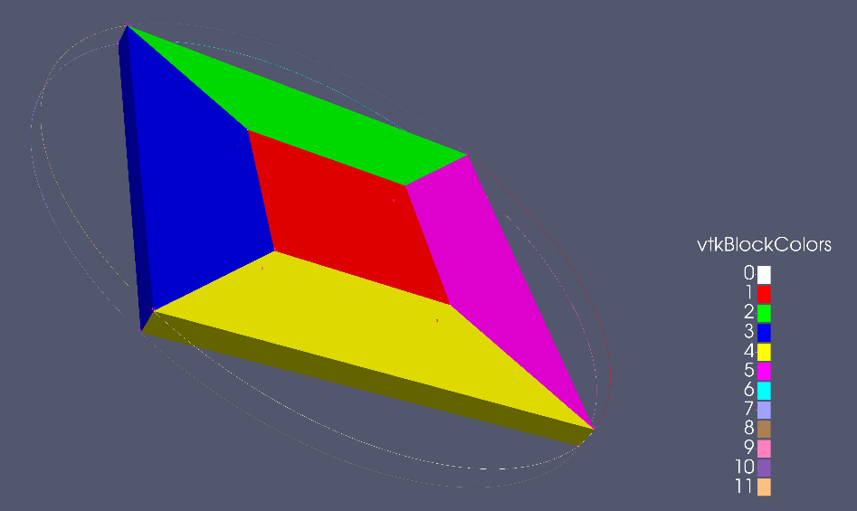
A better solution obtained by simply placing a rectangular inside the circle and dividing the domain by five sub-area as shown in the below figure. The obtained mesh can be classified as structured multi-block mesh.
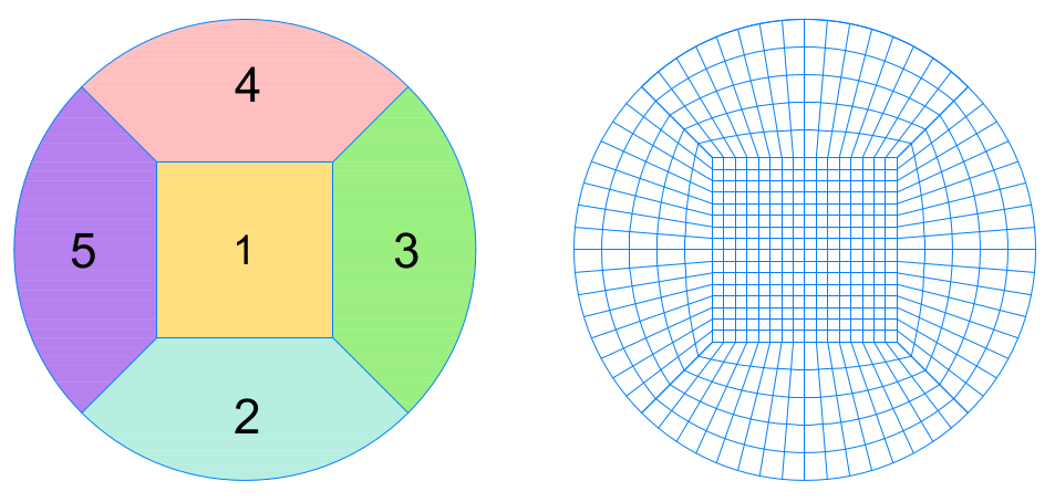
The edge length of the rectangular that is placed inside the circle affects the mesh quality. If the edge length of rectangular is selected relatively small then the mesh is dense inside the rectangular but very coarse in the outside and vice versa. Therefore optimal length for the edge length was needed to be determined and calculated according to the following approach.
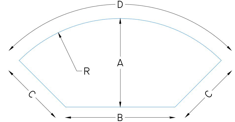
If the sub-area shown below is discretizated such that the optimal mesh is obtained, the ratio of the C to A and B to D must be equal to unity. However it is impossible since the concerned shape is circular. Therefore a compromised solution is to equalize the ratios with each other.
\(\dfrac{A}{C}=\dfrac{B}{D}\Rightarrow B=\dfrac{\left( R-\dfrac{B}{2}\right).\left(\dfrac{\pi R}{2}\right)}{R-\dfrac{B}{\sqrt{2}}}\Rightarrow B^{2}-B.R.\left( \dfrac{\pi}{\sqrt{2}}+2\right)+R^{2}.\pi=0\)
\(R=6.5 \text{ m} \Rightarrow B=\text{Edge of the Rectangular}=6.27\approx 6.5 \text{ m}\)
4.1.3. Generating the Mesh with blockMesh
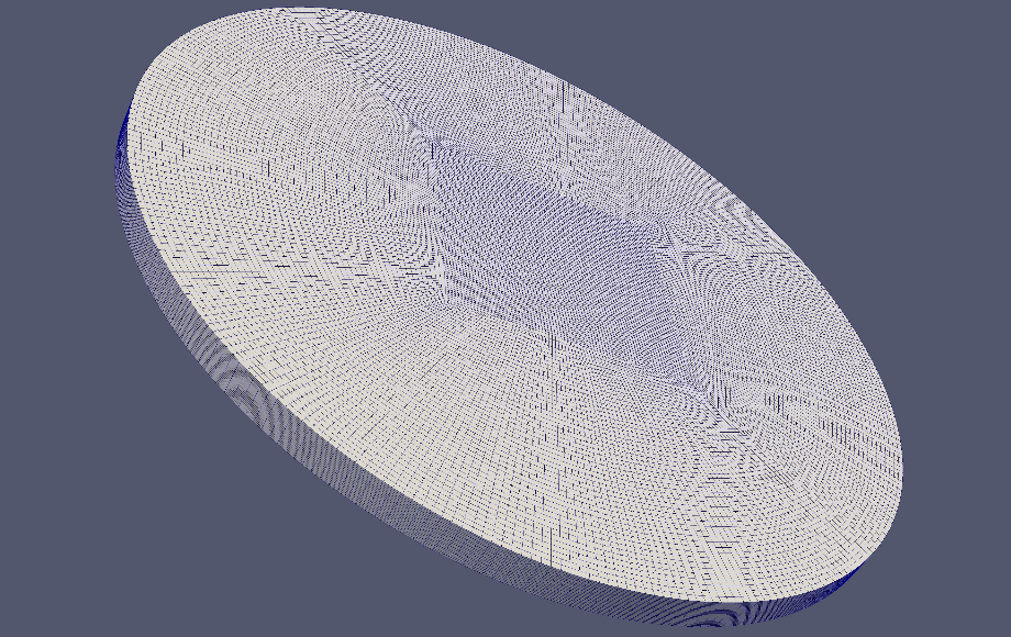
After obtaining the optimal length for the edge of inner rectangular, the domain was divided into cells with an aspect ratio close to unity, by a mesh generator called blockMesh. The blockMesh is a basic and reliable mesh generator of OpenFOAM that can be used for simple and multi-block grid systems. Inputs that are required for the process such as vertices, blocks and special edge definitions are stored in a dictionary called blockMeshDict. First of all, vertices which are the points of intersection for every individual line in sub-areas (Figure 2) were defined in the dictionary. After that, blocks and edge definitons were defined in order to connect specified vertices in accordance with edge definitions.
Finally, specifying the division intervals for the blocks resulted a mesh for the Coriolis Platform. Also a Pytho script was generated to allow the user to modify blockMeshDict file in easy and rapid way.
4.2. Python codes for the mesh
The following script will generate a blockMeshDict file for a multiblock mesh of a cylinder. The mesh will be created with O-H Grid method, therefore it will consist a square block located in the center and four other
Variables :
- r : Radius if the Cylinder
- height : Edge Length of the Inner Rectangular
- l2 : x and y for the First Vertice
- divx : Number of Cells in x Direction
- divy : Number of Cells in y Direction
- divz : Number of Cells in z Direction
- divr : Number of Cells Along Rectangular
Python code for the mesh:
#!/usr/bin/env python

import os
from math import sin, cos, pi
from runpy import run_path

keys_input = ['r', 'height', 'l2', 'divx', 'divy', 'divz', 'divr']


path_in = os.path.join('system', 'input_make_blockMeshDict.py')
if not os.path.exists(path_in):
    raise ValueError('No file ' + path_in)

d = run_path(path_in, {})

for key in keys_input:
    if key not in d:
        raise ValueError('The variable ' + key +
                      'has to be defined in the file ' + path_in)

default_params = {'converttometer': 1, 'zgrading': 50}

for key, value in default_params.items():
    if key not in d:
        d[key] = value


txt = '''
FoamFile
{
version 2.0;
format ascii;
class dictionary;
object blockMeshDict;
}
'''

txt += '''
convertToMeters {k};

vertices
(
( {l2} {l2} 0.0) // NorthEstsq = 0
(-{l2} {l2} 0.0) // NorthWestsq = 1
(-{l2} -{l2} 0.0) // SouthWestsq = 2
( {l2} -{l2} 0.0) // SouthEstsq = 3

( {a} {a} 0.) // NorthEst = 4
(-{a} {a} 0.) // NorthWest = 5
(-{a} -{a} 0.) // SouthWest = 6
( {a} -{a} 0.) // SouthEst = 7

( {l2} {l2} {h}) // NorthEstsqt = 8
(-{l2} {l2} {h}) // NorthWestsqt = 9
(-{l2} -{l2} {h}) // SouthWestsqt = 10
( {l2} -{l2} {h}) // SouthEstsqt = 11

( {a} {a} {h}) // NorthEstsqt = 12
(-{a} {a} {h}) // NorthWestsqt = 13
(-{a} -{a} {h}) // SouthWestsqt = 14
( {a} -{a} {h}) // SouthEstsqt = 15
);

'''.format(l2=d['l2'], h=d['height'], a=d['r']*cos(pi/4), k=d['converttometer'])


txt += '''
blocks
(
//square block
hex (
9 8 11 10
1 0 3 2
)
({divx} {divy} {divz})
simpleGrading (1 1 {zgrading})

//slice1
hex (
13 12 8 9
5 4 0 1
)
({divx} {divr} {divz})
simpleGrading (1 1 {zgrading})

//slice2
hex (
9 10 14 13
1 2 6 5
)
({divx} {divr} {divz})
simpleGrading (1 1 {zgrading})

//slice3
hex (
10 11 15 14
2 3 7 6
)
({divx} {divr} {divz})
simpleGrading (1 1 {zgrading})

//slice4
hex (
11 8 12 15
3 0 4 7
)
({divx} {divr} {divz})
simpleGrading (1 1 {zgrading})

);
'''.format(divx=d['divx'], divy=d['divx'], divz=d['divz'], divr=d['divr'],
        zgrading=d['zgrading'])


txt += '''
//create the quarter circles
edges
(
arc 4 5 (0.0 {r} 0.0)
arc 5 6 (-{r} 0.0 0.0)
arc 6 7 (0.0 -{r} 0.0)
arc 7 4 ({r} 0.0 0.0)

arc 12 13 (0.0 {r} {h})
arc 13 14 (-{r} 0.0 {h})
arc 14 15 (0.0 -{r} {h})
arc 15 12 ({r} 0.0 {h})

);'''.format(r=d['r'], h=d['height'])

txt += '''
patches
(

wall surface
(
(8 11 10 9)
(8 12 15 11)
(12 8 9 13)
(9 10 14 13)
(11 15 14 10)
)

wall bottom
(
(0 3 2 1)
(0 4 7 3)
(4 0 1 5)
(1 2 6 5)
(3 7 6 2)
)

wall walls
(
(5 4 12 13)
(5 13 14 6)
(6 14 15 7)
(7 15 12 4)
)

);'''

print(txt)

path = os.path.join('system', 'blockMeshDict')
print('save new blockMeshDict in path\n' + path)

with open(path, 'w') as f:
    f.write(txt)
4.3. Spinup Strat Piece Mesh
In this simulation the calculus domain has been restricted to a small “piece of cake”. The idea behind the restriction was to have a fast runningsimulation that will allow us to test various mesh configurations and choose the one that best fitted our model.
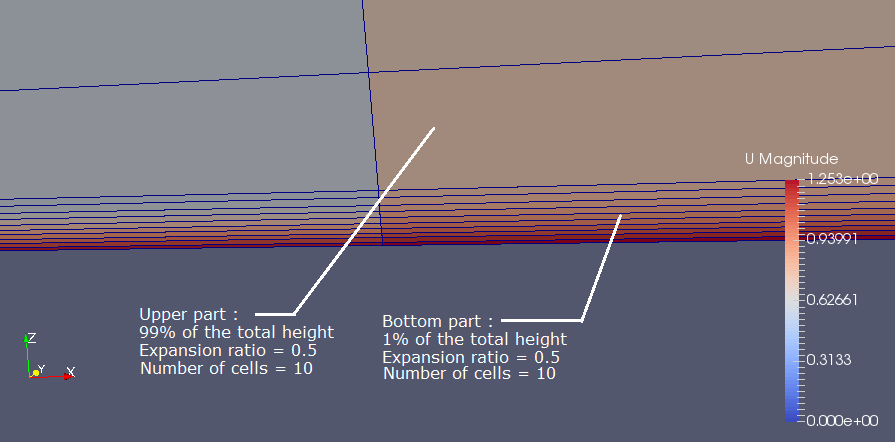
We then wrote a Python mesh generating script for this particular tutorial. In order to have at least 10 cells calculated in the boundary layer and to have very small cells near the bottom wall, we chose to split the z axis into two zones. One zone near the wall that has an expansion ratio of 0.2 (see annex for details and definitions), and an upper zone that has a uniform discretisation. We made sure that the center of the first cell is in the sub-viscous layer. We also wanted to have a simulation that runs as fast as possible, so we reduced the width of the “piece of cake” to 3 mm (3 cells, width = 1 mm) in order to have something that is almost 2D like.
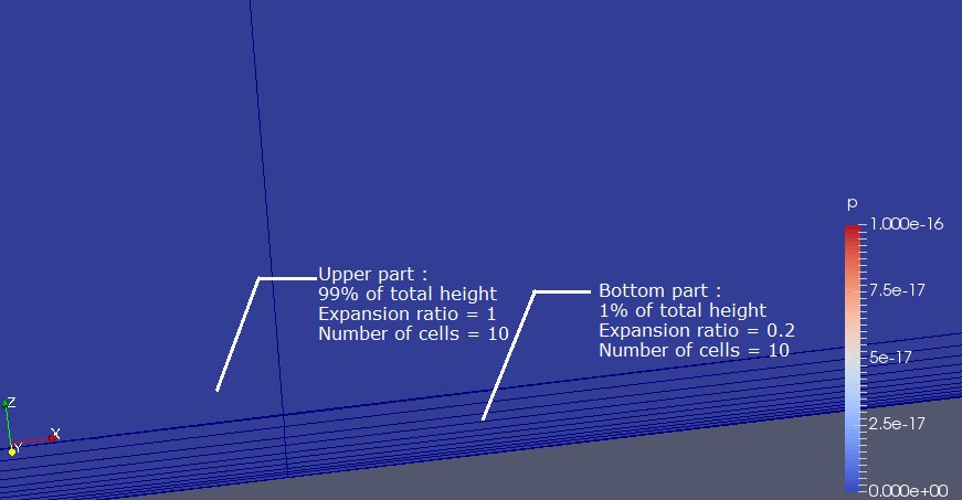
We tried to run a simulation with water using this calculus domain and this mesh, but it did not work, since it completely diverged. The fact that the simulation failed is due to the enormous difference of sizes between the upper and the lower part of the z axis (ratio of 10 000), and the very important aspect ratios on each cell (more than 100).
To solve this issue, we decided to make a wider piece, we choose the width of the cell in order to have an aspect ratio of about one for the upper cells (total width = 7.5 cm, 3 cells). We also choose to put a gradient in the upper part of the z axis to have less differences in size between the last cell of the bottom part and the first cell of the upper part.